Sunday, December 12, 2010

Wiring Loom Removal

Now onto removing the writing loom. I have already disconnected the charging and ignition systems:


and I've removed the regulator and rectifier units along with the toolholder


The flasher relay is held next to the reservoir for the linked brake system, under the seat and in front of the battery:


Two sub-looms are strapped together on the right hand side of the frame, and run along the breather box:


The fuse box:

 rear of the fusebox:
 The fusebox is held in place by two screws that are held by two nuts welded to the frame brackets
 Starter motor relay
 Battery connections:

Neutral indicator switch

Starter and headlamp flasher relays 


Oil pressure warning switch:

Loom removed!


Linked Brake Disassembly

Well, the linked brake unit is a bit of a dog's dinner compared to the system on the T-series big twins. Here is the assembled master cylinder. On the right is the connecting rod that goes to the foot lever. In the middle is a hydraulic hose that goes to the brake fluid reservoir, which is under the seat, and in front of the battery. On the left is a banjo bolt that takes brake juice to the rear brake, through a normal sizes hose, and to the front linked brake via a narrow bent pipe. This pipe is formed to the shape of the frame, and ultimately connects to standard brake hose to go to the front left caliper. At the top is the brake light switch.


View of brake linkage


Rear brake caliper has already been removed, but has not yet been drained.


Undo the banjo and drain the system. A bit messy.


The master cylinder js held on by two bolts. There are captive nuts welded onto the frame.

Showing the removed master cylinder next to its mounting points:


The brake footpedal is held in place by a small split pin, which can be removed with nosey pliers to remove the foot control.


At the front of the frame, the linked front brake host and carb cables go through a grommet with loop which acts like a cable tie:


This is the junction where the thin metal pipe turns into proper brake host:


Metal brake pipe has its own fancy rubber spacers that keep it slightly away from the frame:


The bent metal pipe once removed


The flasher relay is mounted in a rubber support that mounts next to the linked brake reservoir:

Removal is easy


Note the rubber strap that holds the tank in place, and the middle piece that provides a mounting for the flasher relay


The removed reservoir and battery strap.


Saturday, December 11, 2010

Front End Wiring

With the fork yokes removed, let's look at the wiring that emerges from the alternator cover. Two groups of wires emerge. One is the alternator output, that goes to the separate rectifier/regulator units that sit on either side of the toolholder behind the battery. The other is from the Dyna electronic ignition that a previous owner wisely installed. See? I'm not just nasty about POs ;-) 

The wiring with the woolly covering is the charging circuit:


Note that two wires go nowhere. I have not disconnected these, they just didn't go anywhere! Note the plastic connector which breaks the loom into two sections:


The front horn as its own wiring loom, which piggybacks on the charging circuit loom. I removed the front horn:

And disconnected the alternator/horn wiring loom at the plastic connector. Then, onto the ignition circuit. The Dyna electronic ignition has three wires, in a grey harness. The wires are colored red, black and white. The black wire connects to the orange wire which goes to the rear of the Left hand (as you sit on the bike) ignition coil. The white wire is connected to another orange wire, which goes to the rear of the left-hand ignition coil:


The red wire goes to a connector to the battery (so it is the 'power in' connector). Some complex (and slightly dodgy) connections split the power-in between the two ignition coils and the red line to the Dyna unit.


Front Yoke

With the forks removed, its time to remove the fork yokes (triple tree). Here's some shots of the yokes before I did anything:


Just unscrew the top bolt:


Note the spacer with a tang that locates in the top yoke:

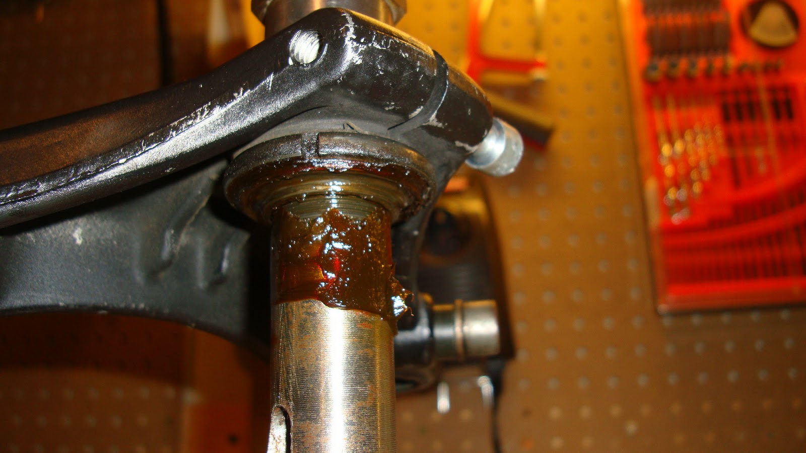
Can't believe anybody would design a bearing with open ball bearings. This is truly horrible:


Note the adjustment ring below the top yoke:


These will be replaced by the Guzzitech alternative when it's rebuild time!

Front Fork Update

I sprayed the front fork bolts that I couldn't shift with WD40 and left them to soak for a week. The right hand one cracked easily after that, so I could take the slider off the fork leg no sweat. Sadly the LHS just will not shift, so I took the whole leg off as one piece and will return to it later.

Here's the leg that would come apart:


These are the fairing mounts. Note the rubber isolators top and bottom.


Clip-ons are about as simple as clip-ons can be:


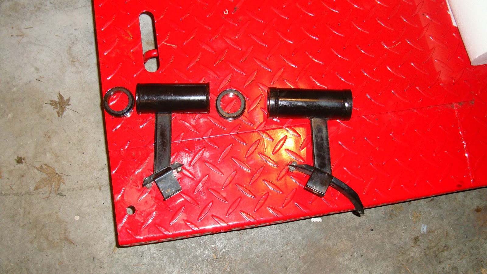
These brackets were between the bottom of the clip-ons and the top mounting rubber of the fairing mounts. These are used to mount the instrument cluster.