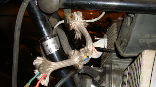
With the fork yokes removed, let's look at the wiring that emerges from the alternator cover. Two groups of wires emerge. One is the alternator output, that goes to the separate rectifier/regulator units that sit on either side of the toolholder behind the battery. The other is from the Dyna electronic ignition that a previous owner wisely installed. See? I'm not just nasty about POs ;-)
The wiring with the woolly covering is the charging circuit:
Note that two wires go nowhere. I have not disconnected these, they just didn't go anywhere! Note the plastic connector which breaks the loom into two sections:
The front horn as its own wiring loom, which piggybacks on the charging circuit loom. I removed the front horn:
And disconnected the alternator/horn wiring loom at the plastic connector. Then, onto the ignition circuit. The Dyna electronic ignition has three wires, in a grey harness. The wires are colored red, black and white. The black wire connects to the orange wire which goes to the rear of the Left hand (as you sit on the bike) ignition coil. The white wire is connected to another orange wire, which goes to the rear of the left-hand ignition coil:
The red wire goes to a connector to the battery (so it is the 'power in' connector). Some complex (and slightly dodgy) connections split the power-in between the two ignition coils and the red line to the Dyna unit.


No comments:
Post a Comment